| Number of inputs and outputs |
Number of digital outputs: 2; Number of analogue outputs: 1 |
| Process connection |
threaded connection G 1/4 internal thread DN8 |
| Absolute |
|
| Measuring range |
0...400; (depending on the nozzle used) |
| Application |
for industrial applications |
| Media |
compressed air |
| Medium temperature |
-10...60 |
| Min. bursting pressure |
|
| Pressure rating |
|
| Operating voltage |
18...30 DC; (to SELV/PELV) |
| Current consumption |
< 80 |
| Protection class |
III |
| Reverse polarity protection |
yes |
| Power-on delay time |
1 |
| Number of inputs and outputs |
Number of digital outputs: 2; Number of analogue outputs: 1 |
| Inputs |
teach input |
| Output signal |
switching signal; analogue signal; IO-Link; (configurable) |
| Electrical design |
PNP/NPN |
| Number of digital outputs |
2 |
| Output function |
normally open / normally closed; (parameterisable) |
| Max. voltage drop switching output DC |
2.5 |
| Permanent current rating of switching output DC |
150; (per output) |
| Number of analogue outputs |
1 |
| Analogue current output |
4...20; (scalable) |
| Max. load |
500 |
| Short-circuit protection |
yes |
| Type of short-circuit protection |
pulsed |
| Overload protection |
yes |
| Absolute |
|
| Measuring range |
0...400; (depending on the nozzle used) |
| Setting range |
0...500; (depending on the nozzle used) |
| Resolution |
1 |
| Set point SP |
2...500 |
| Reset point rP |
0...498 |
| Analogue start point ASP |
0...400 |
| Analogue end point AEP |
100...500 |
| In steps of |
1 |
| Relative (without unit of measurement) |
|
| Measuring range |
0...800 |
| Setting range |
0...1000 |
| Resolution |
1 |
| Set point SP |
4...1000 |
| Reset point rP |
0...996 |
| Analogue start point ASP |
0...800 |
| Analogue end point AEP |
200...1000 |
| In steps of |
1 |
| Pressure monitoring |
|
| Measuring range |
-1...16 |
| Display range |
-1...20 |
| Resolution |
0.05 |
| Set point SP |
-0.92...16 |
| Reset point rP |
-1...15.92 |
| Analogue start point |
-1...12.8 |
| Analogue end point |
2.2...16 |
| In steps of |
0.01 |
| Flow monitoring |
|
| Measuring range |
| 0.8...100 l/min | 0.3...33.2 m/s | 0.05...6 m³/h |
|
| Display range |
| 0...120 l/min | 0...39.8 m/s | 0...7.2 m³/h |
|
| Resolution |
| 0.2 l/min | 0.1 m/s | 0.01 m³/h |
|
| Set point SP |
| 1.4...100 l/min | 0.5...33.2 m/s | 0.08...6 m³/h |
|
| Reset point rP |
| 0.9...99.5 l/min | 0.3...33 m/s | 0.05...5.97 m³/h |
|
| Analogue start point ASP |
| 0...80 l/min | 0...26.6 m/s | 0...4.8 m³/h |
|
| Analogue end point AEP |
| 20...100 l/min | 6.6...33.2 m/s | 1.2...6 m³/h |
|
| Low flow cut-off LFC |
| 0.6...1 l/min | 0.2...0.3 m/s | 0.04...0.06 m³/h |
|
| In steps of |
| 0.1 l/min | 0.1 m/s | 0.01 m³/h |
|
| Accuracy (in the measuring range) |
± (5% MW + 5 µm); (pressure 1...3 bar) |
| Repeatability |
± (3% MW + 2 µm); (pressure 1...6 bar) |
| Pressure monitoring |
|
| Repeatability |
± 0,2 |
| Characteristics deviation |
< ± 0,5; (BFSL = Best Fit Straight Line) |
| Greatest TEMPCO of the span |
± 0,3 |
| Greatest TEMPCO of the zero point |
± 0,1 |
| Flow monitoring |
|
| Temperature coefficient |
± 0,07 % MW |
| Accuracy (in the measuring range) |
class 141: ± (2 % MW + 1 % MEW); class 344: ± (6 % MW + 1,2 % MEW) ; air quality to ISO 8573-1:2010; at medium temperature 23 °C |
| Repeatability |
± (0,8 % MW + 0,4 % MEW) |
| Pressure monitoring |
|
| Response time |
0.05 |
| Flow monitoring |
|
| Response time |
0.1; (dAP = 0) |
| Damping process value dAP |
0...5 |
| Parameter setting options |
hysteresis / window; normally open / normally closed; current output; display can be rotated and switched off; Display unit; Teach function |
| Communication interface |
IO-Link |
| Transmission type |
COM2 (38,4 kBaud) |
| IO-Link revision |
1.1 |
| SDCI standard |
IEC 61131-9 |
| SIO mode |
yes |
| Required master port type |
A |
| Process data analogue |
7 |
| Process data binary |
2 |
| Min. process cycle time |
7.2 |
| Supported DeviceIDs |
| Type of operation | DeviceID | | default | 1333 |
|
| Note |
| For further information please see the IODD PDF file under "Downloads" |
|
| Ambient temperature |
0...60 |
| Storage temperature |
-20...85 |
| Max. relative air humidity |
90 |
| Protection |
IP 65; IP 67 |
| EMC |
|
| Vibration resistance |
| DIN EN 68000-2-6 | 5 g (10...2000 Hz) |
|
| MTTF |
167 |
| UL approval |
| UL Approval no. | I012 | | File number UL | E174189 |
|
| Pressure Equipment Directive |
Sound engineering practice; can be used for stable gases fluid group 2 |
| Weight |
548.2 |
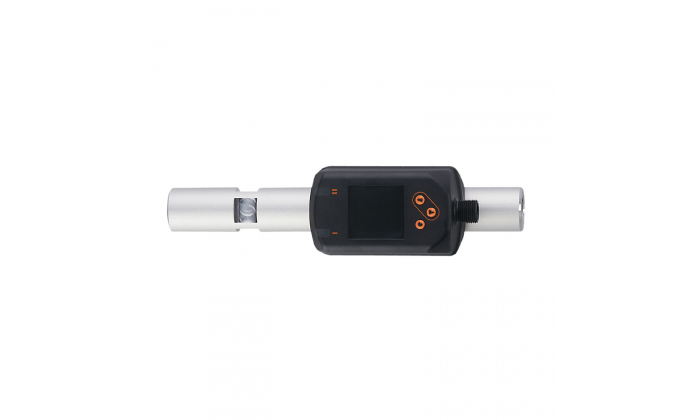
| Housing |
rectangular |
| Dimensions |
182 x 45.4 x 67.8 |
| Materials |
PBT+PC-GF30; PPS GF40; stainless steel (304/1.4301); stainless steel (303/1.4305); steel (1.5523) galvanised; 2.0401 (brass / CW614N); FKM |
| Materials (wetted parts) |
EN AW-6082 (aluminium); stainless steel (303/1.4305); FKM; ceramics glass passivated; PPS GF40; Al2O3 (ceramics); acrylate; SINT-A51; stainless steel (304/1.4301); CW510L (brass) |
| Process connection |
threaded connection G 1/4 internal thread DN8 |
| Display |
| colour display 1,44", 128 x 128 pixels | | 2 x LED, yellow |
|
| Remarks |
| MW = measured value | | MEW = Final value of the measuring range | | Measuring, display and setting ranges refer to the standard volume flow according to DIN ISO 2533. | | For information about installation and operation please see the operating instructions. |
|
| Pack quantity |
1 pcs. |
| Connection |
Connector: 1 x M12; coding: A |